

BMW E39 Navigation Retrofit Project
Table of Contents
- Main
- Software Design
- Arduino Power Board
- Video Switch + Backup Camera Install
- Rpi Construction
- Bill of Materials
- References
Arduino Power Board
Introduction
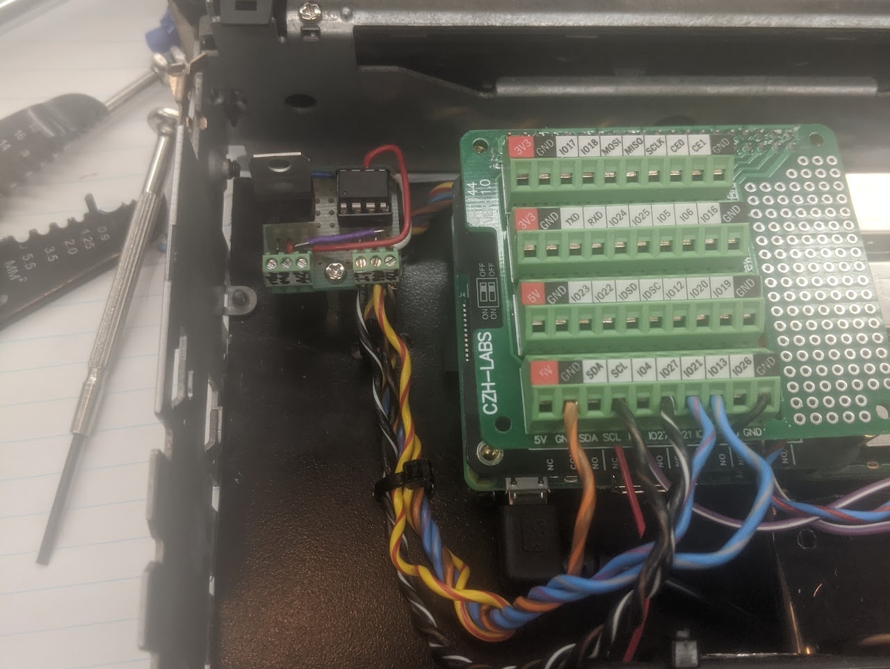
To turn the Pi 3B+ on and off, I made a small board using an ATTiny85 and the Sparkfun Tiny AVR Programmer
The Pi turns on when the I2C SCL pin is pulsed to ground, and the PEN (Power-ENable pin) is not grounded. The Pi is configured to initiate a software shutdown when GPIO27 has a falling edge.
Because I chose to use an I2C Relay Board, I needed to leave the SCL pin floating from the ATTiny perspective so that the I2C clock would still work. For this reason, I couldn’t take a shortcut and use the relay to simply ground the SCL pin while the Pi should be on.
The Arduino logic monitors an input pin for change in switched accessory state, and drives the Pi on or off. When shutting down it has a timer to wait for the Pi to safely shutdown.
In a future release, I would like to remove the polling logic from the Arduino and use a pin change interrupt. However, in my testing with ISRs, I ran into trouble debouncing the pin-change interrupts to only activate the ISR on a falling edge. By switching to an interrupt-based approach, I can further reduce the power consumption of the ATtiny85.
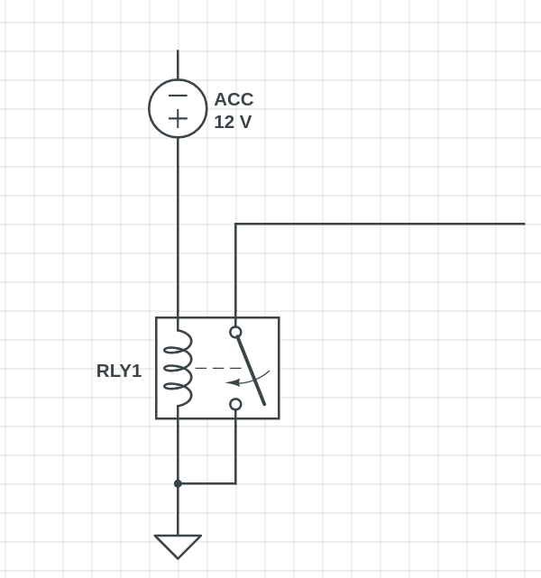
ACC Relay Logic
The black relay in the Pi box is turned on when the switched accessory power is turned on. It grounds an input pin to the ATTiny85 that is continuously checked.
The ATTiny85 is always powered on from the car battery.
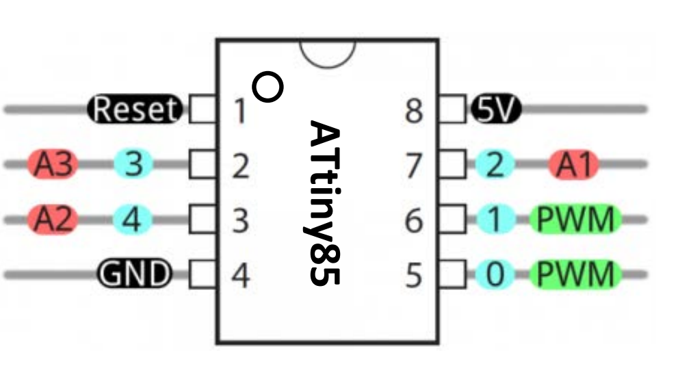
ATTiny85 Pinout
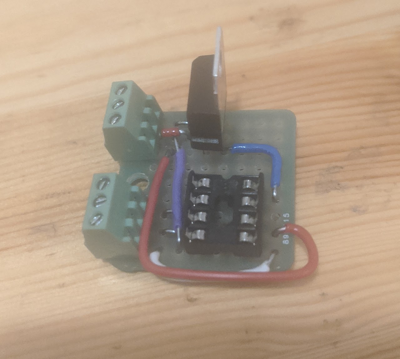
The board above is just a breakout board for the ATTiny85, with each pin going to a screw terminal, and a 7805 voltage regulator converting +12V (switched) to 5v.
Board Screw Terminals
- +12V
- Ground
- Ignition Sense Pin (Attached to Relay as shown above)
- GPIO27 (Falling edge to turn off Pi)
- SCL (I2C clock. Ground to turn on pi)
- PEN (Rpi Power Enable)
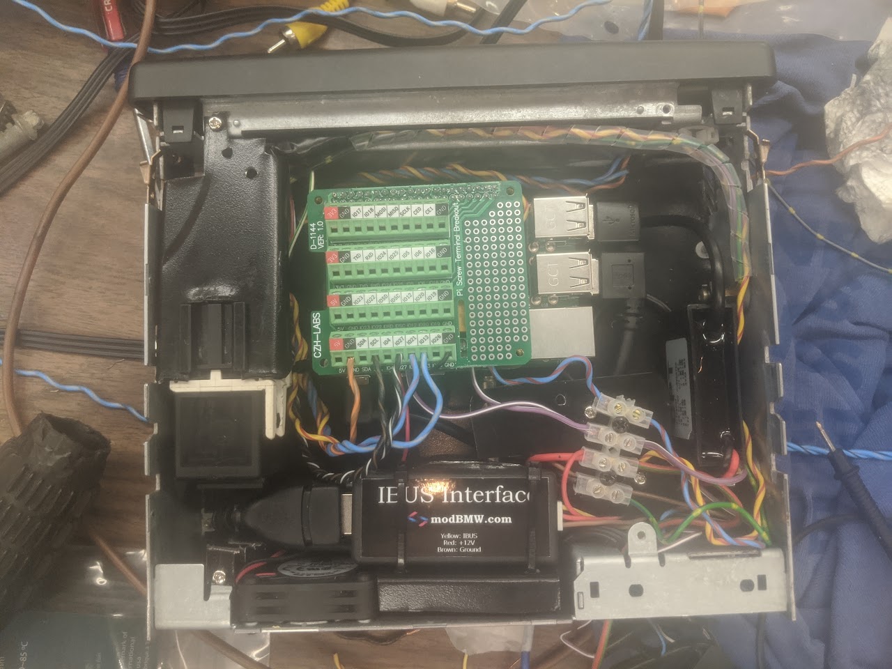
Pictures
Links
https://cdn.sparkfun.com/assets/2/8/b/a/a/Tiny_QuickRef_v2_2.pdf https://www.sparkfun.com/products/11801