BMW E39 Navigation Retrofit Project
Table of Contents
- Main
- Software Design
- Arduino Power Board
- Video Switch + Backup Camera Install
- Rpi Construction
- Bill of Materials
- References
Rpi Construction
Introduction
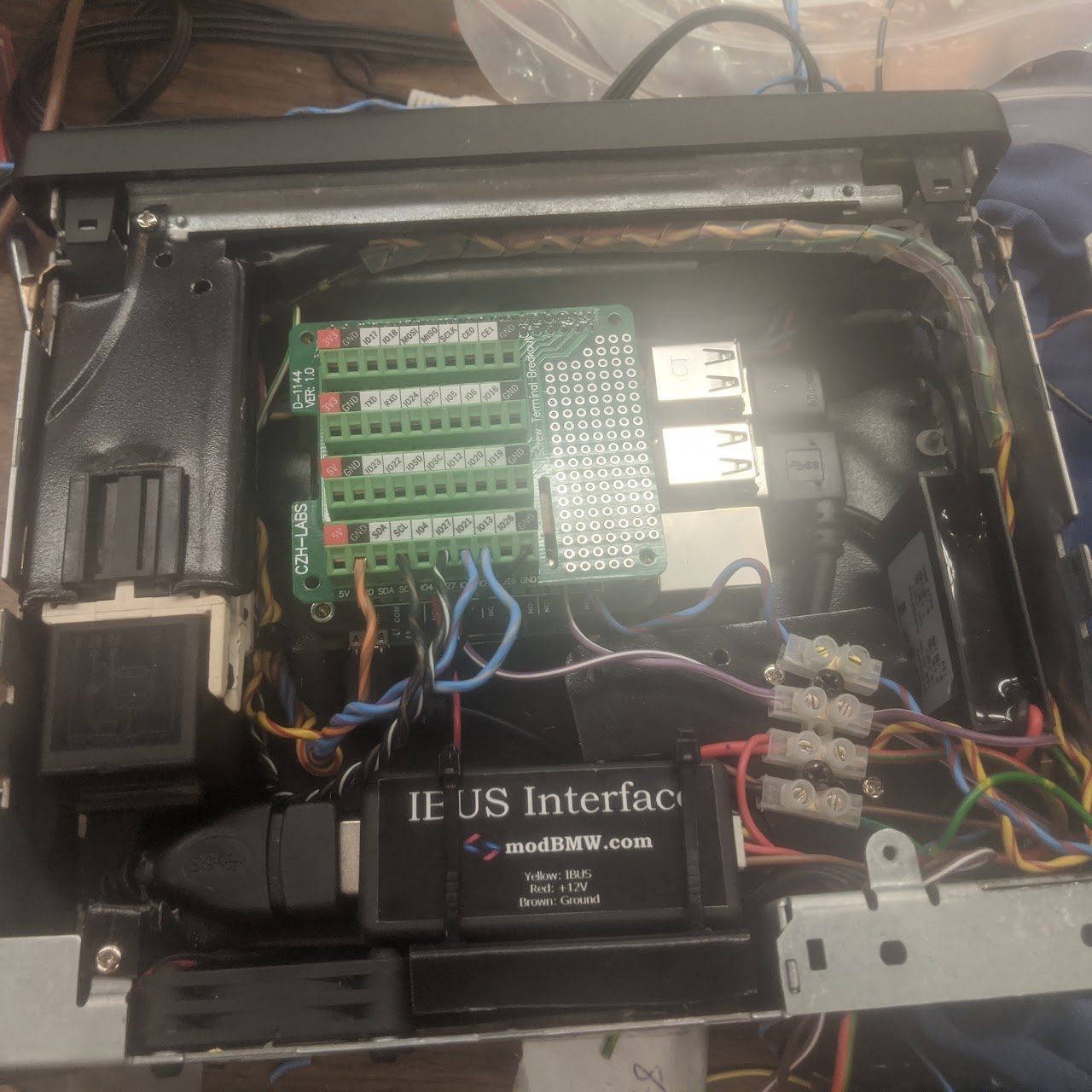
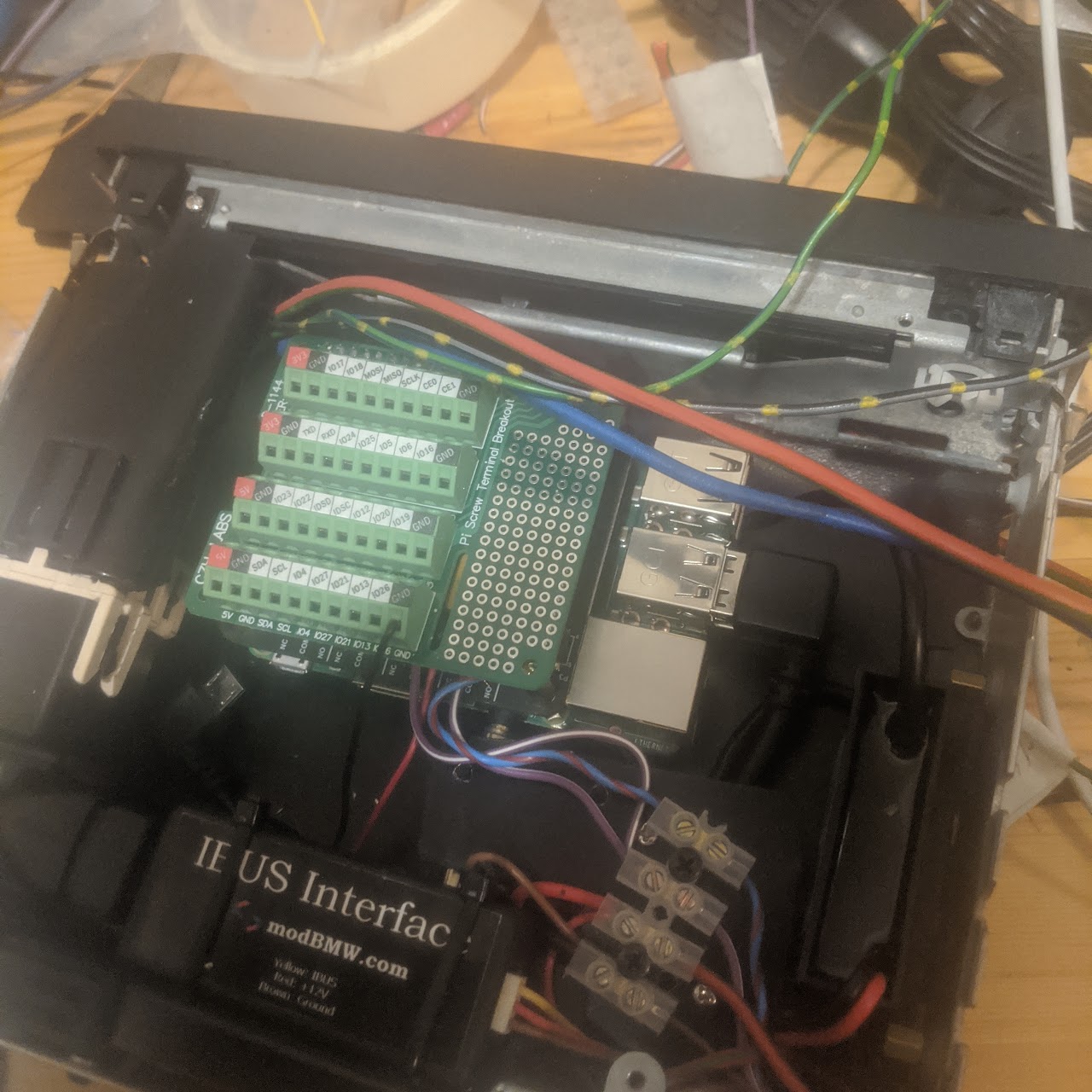
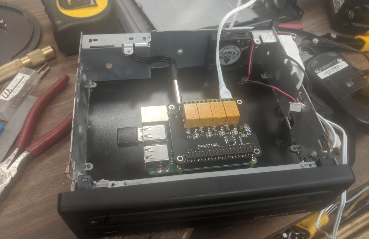
The RPi system contains a relay board and a GPIO breakout board mounted on the 40pin HAT header.
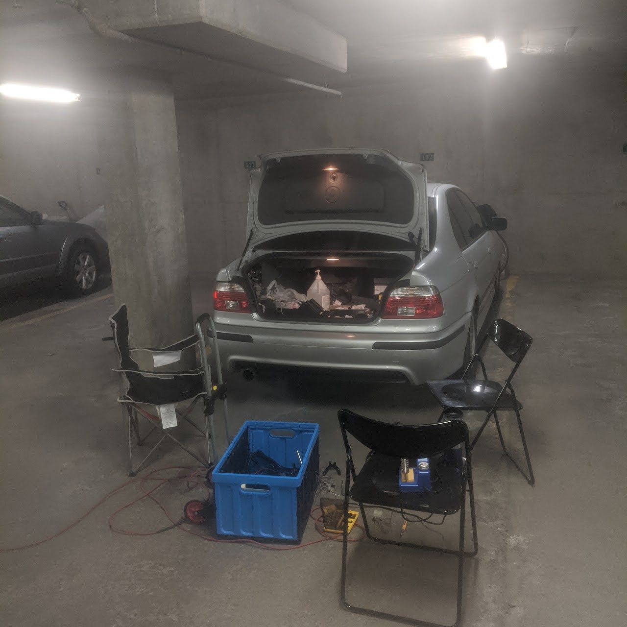
The Pi is continuously supplied with power (even while the car is off) by a 12v -> 5v power supply. For this reason, the Arduino RPi Power Switch turns the Pi on and off with the ignition state of the car, and puts the RPi into low-power mode while the car is off. This is so that the car battery does not drain (as quickly) while the car is off.
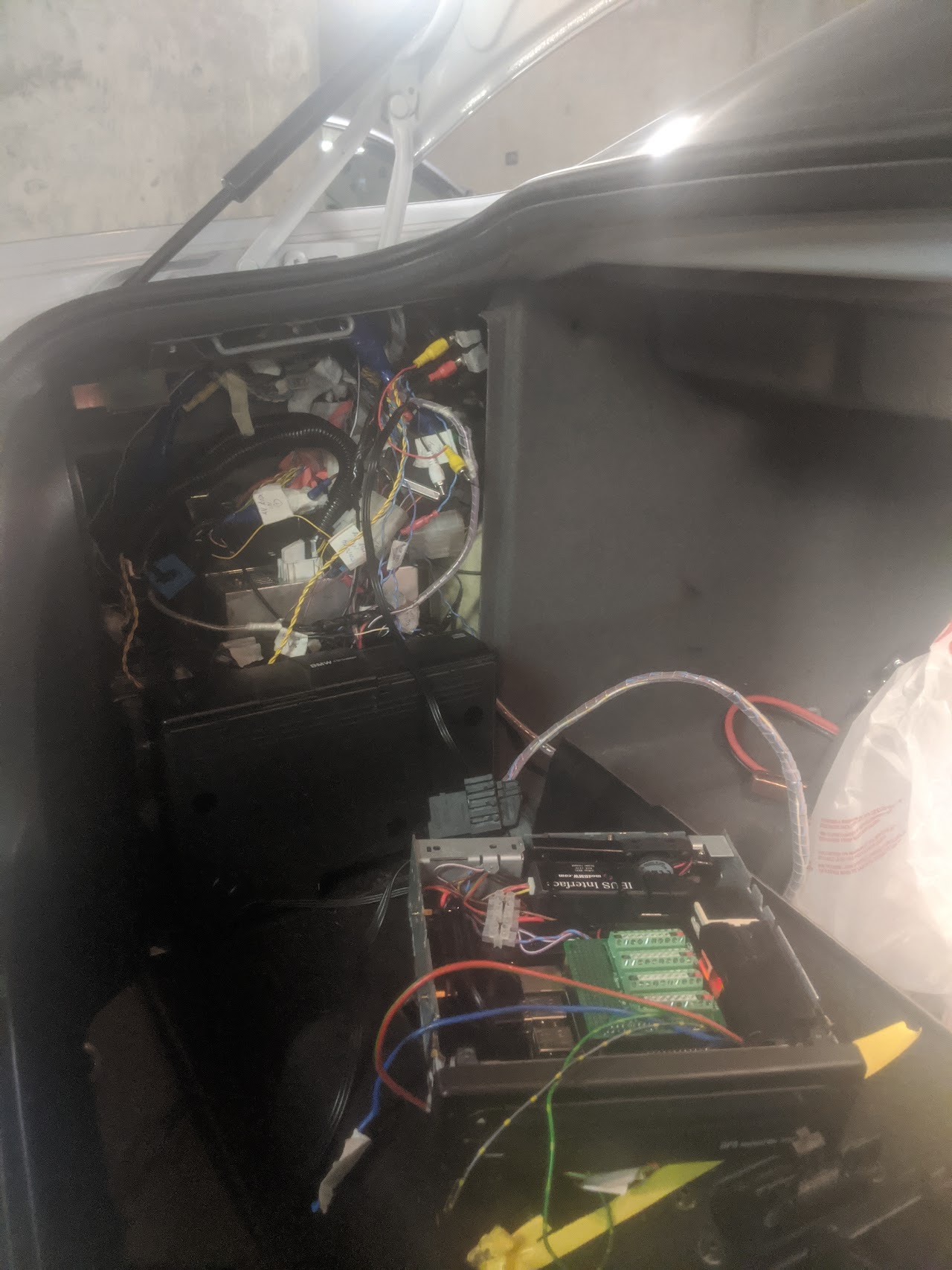
The communication to the rest of the car is provided by the ModBMW IBus USB Serial Interface.
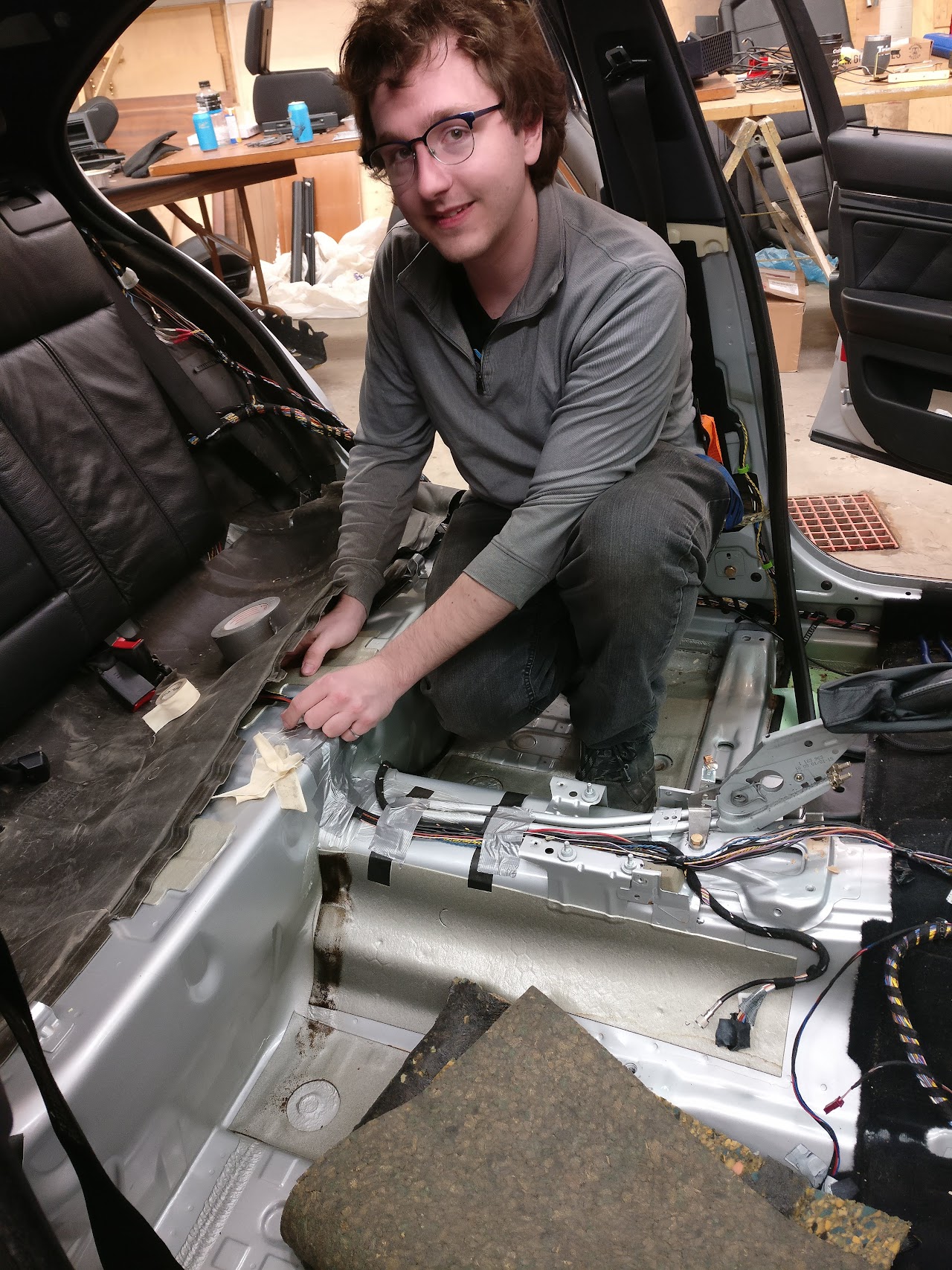
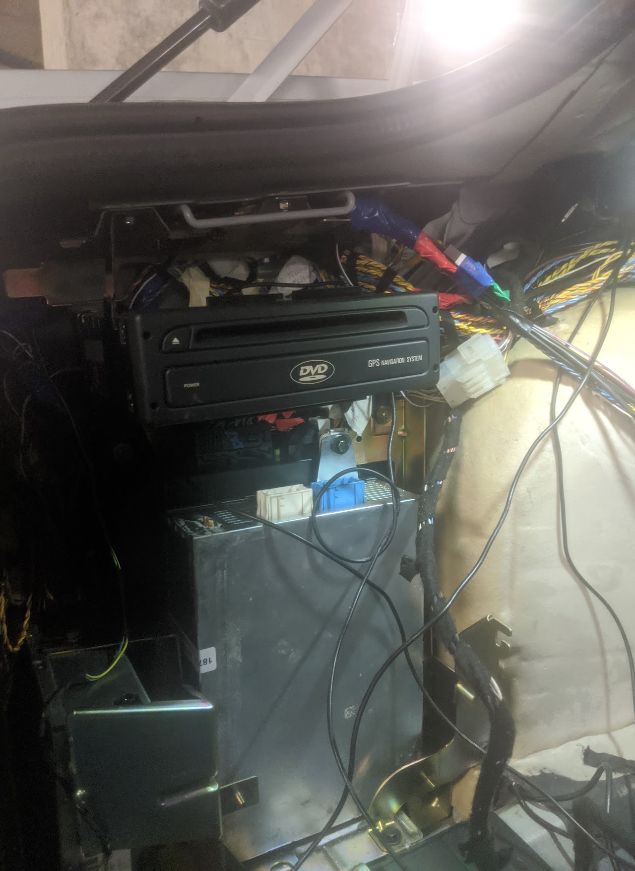
The Pi is connected to the rest of the car via the TV Module Harness I made.
The Pi relay board allows the Pi to turn on it’s own video output in software, and it allows it to turn on the 12V cooling fan in it’s case.

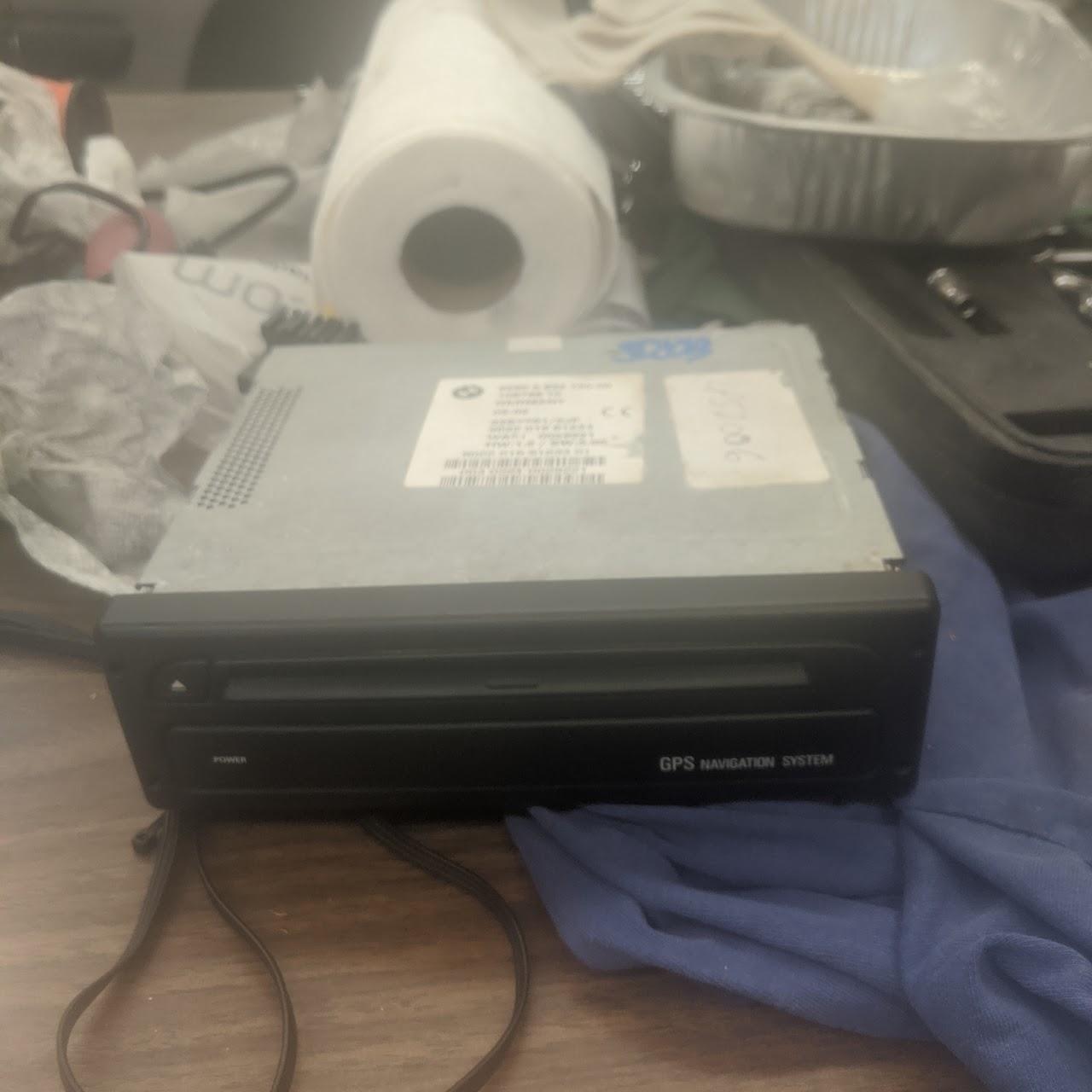
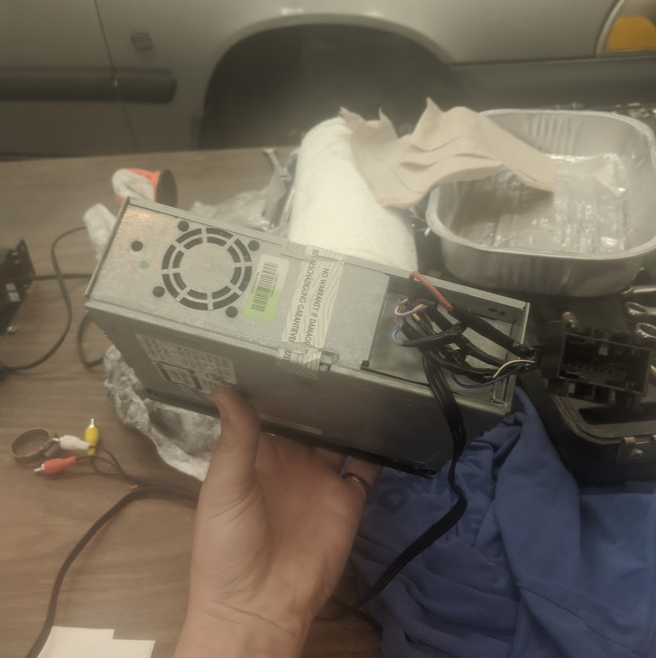
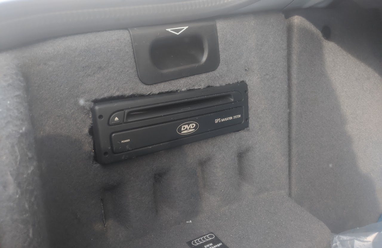
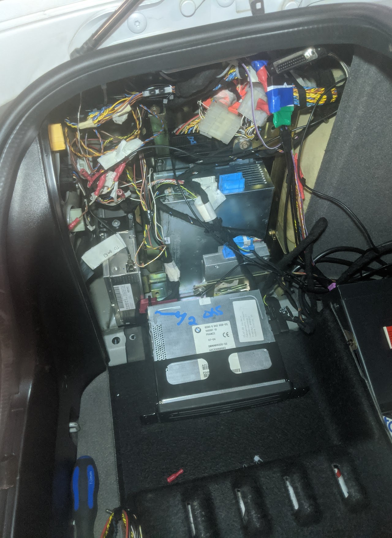
To construct the Pi enclosure, I used a water-damaged Mk3 navigation drive I sourced from Buck’s Auto. I also wired up the case’s status LED and eject button to the RPi’s GPIO pins.
All of the black sheet metal inside the Pi is the exterior casing of a microwave.
Pictures